
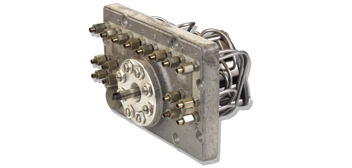
T-Pump
– for the lubrication of medium- and large-sized diesel engines and compressorsOil lubrication pump T (up to max. 180 bar)
Available with either pressure-tight or vented reservoirs. In the pressure-tight version (Type TA), oil is supplied to the reservoir from an elevated supply tank or a pressurized oil circuit. Maximum supply pressure: 2 bar. An inlet port with a G 1/2" internal thread is located on the rear wall of the housing. In the non-pressurized version (Type TB), the vented reservoir is filled manually after removing the filler cap.
Pumps with a 4-liter housing (T..4...) feature a housing cover and a pump assembly (max. 8 pump elements).
Standard version
- Modes of driving: direct drive rotating or oscillating or electrical motor
- For oil and emulsion
- Drop sight control (max. 8 Lubrication points)
- For minimum quantity lubrication of 1 to 16 points of lubrication
- Maximum delivery rates of 0,17 to 0,52cm3 per stroke on each lubrication point.
- Admissible operating pressure max. 180 bar
Special version
- with monitoring unit
- with manuel pre lubrication
- with heating facility
The lubricating pump shaft (SW) is moved from outside the container (3). It moves the gear shaft (59) via the helical gear wheel (197) and the intermediary coupling (50). The chosen transmission between lubricating pump shaft and helical gear wheel produces the desired number of revolutions of the gear shaft. The gear shaft carries the work disk (41) and the control disk (43) which move the operating pistons (AK) as well as the control pistons (SK) in the pump bodies (51...58). The pump bodies are arranged in a circle around the gear shaft and screwed on a firmly fixed base plate (45). Each pump body is equipped with a suction pipe (SL) and one or two pressure pipes (DL), the latter leading to the outlet in the casing cover (31). The operating and control pistons with their jaw-shaped, upper end encompass the edge of the cam disks (41, 43). The double-stage work disk moves the operating pistons up and down twice with each revolution of the gear shaft. The width between jaws of the operating pistons (and thus stroke and pump capacity) can be regulated by means of the adjusting screws (32 resp. VS). Twisting to the left increases the pump capacity. The control pistons regulate the oil flow through the pump body. In case of pump bodies with two pressure pipes the operating pistons push oil alternately into the upper and the lower pressure pipe with each revolution of the gear shaft. The control disk is single-stage. In case of pump bodies with one pressure pipe, one revolution of the gear shaft causes the operating pistons to push oil twice into the same pressure pipe. The control disk is double-stage. Within one pump set only pump bodies with either one or two pressure pipes can be used. Regulation of pump capacity of the individual pump bodies is effectuated after removal of the cap (36) by means of the adjusting screws arranged in a circle around the gear shaft.
Twisting to the right results in a reduction of pump
capacity by approx. 30%. To this effect, the adjusting
screw has to be moved by approx. 20 grooves.
On request, pump bodies with a wider regulating
range (up to 0 cm3/stroke) can be installed.
In case of pump bodies with two pressure pipes, regulation
of pump capacity is effectuated jointly for
two outlets.
For pumps of type TB... (ventilated), equipped with pump bodies with two outlets, the function of the pump bodies can easily be controlled optically: one of the two pressure pipes conveys to the drop control in the cover and back into the container.
For pumps of type TA... (pressure-proof), the oil flow in the individual pressure pipes is controlled by means of optical flow controls SP/SFZ... . These control devices can be installed at the pressure outlets of the lubricating pumps or at any position in the lubricating pipes. Electrical control of the oil flow can be performed by means of flow control SP/SFE 30... In case of flow interruption the impulse monitoring device transmits an electrical signal. The flow control (impulse generator) can be installed at any position in the pressure pipe.
